
Compared to the mechanisms of heat transfer by conduction and convection, heat transfer by radiation has its own unique characteristics. For instance, radiation does not require any medium to transport heat over huge distances, and it is the dominant effect at very high temperatures. Also, radiation depends on direction, wavelength, and temperature. Ever wonder which interface in the COMSOL Multiphysics® software you should use to best account for radiation in your model? Keep reading…
The Characteristics of Thermal Radiation
In a previous blog post, we discuss how radiation is often nonnegligible. Here, we give comprehensive guidelines for modeling radiation, take a look at what makes radiation so special, and discuss the different interfaces for different use cases.
The source of thermal radiation is all matter with a temperature above absolute zero. For heat transport, radiation in the infrared range in particular, but also in the range of visible light, plays a major role.
Our best known source of thermal radiation is the Sun. That said, we discover the first peculiarity of thermal radiation — it can travel over very large distances. Radiation does not need any matter to be transferred from one object to another, but the interaction with matter turns the electromagnetic wave into heat. From its almost unhindered way from the Sun to the Earth, the action takes place as the radiation enters Earth’s atmosphere, where the high number of molecules absorbs and scatters the incoming radiation depending on the wavelength \lambda (m). The remaining transmitted part hits Earth’s surface and is absorbed and reflected depending on the surface properties.
From this example, we notice three different kinds of matter, illustrated in the below figure.
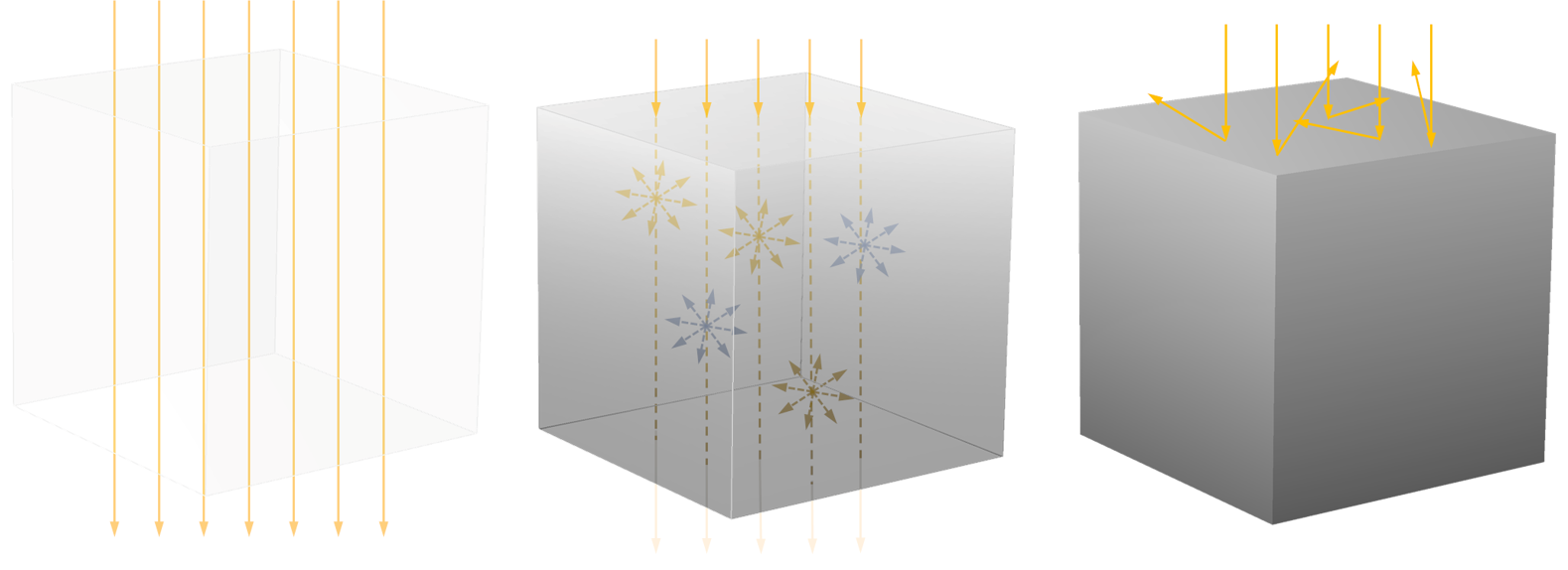
Left: Radiation traveling unhindered through a transparent medium. Center: Partially absorbed, scattered, and emitted radiation in a participating medium. Right: Radiation reflected on the fully reflecting surface of an opaque medium.
Transparent
Matter that allows radiation to travel through it is called transparent. Perfectly transparent matter is only vacuum, but it is also a good assumption for gases at low to moderate temperatures or small distances. When we are dealing with a transparent medium, there is no interaction with radiation, hence there is also no heat transport due to it.
Opaque
In general, materials are called opaque if they completely absorb incident radiation over a very short distance. Hence, it not only depends on the material properties alone but also on the thickness of the object.
For many solids, the distance to complete absorption is only a few ångström (\AA); e.g., for metals. In this case, the term surface radiative transfer is used and the surface properties play a major role (polished vs. carbonized metal). An opaque surface can be described by its emissivity \varepsilon and its diffuse and specular reflectivity \rho_\textrm{d} and \rho_\textrm{s}.
Participating
Participating materials interact with the radiation through (partial) absorption and scattering. Often, participating media also emit radiation, which is especially true if particles or bubbles are present. For a given wavelength, the medium emits similarly as it absorbs. The presence of particles or bubbles enhances this interaction and thus also the emission in the medium. The amount of absorbed intensity is proportional to the radiation intensity and the emitted intensity is proportional to the blackbody intensity at the medium temperature. Scattering of radiation only changes the direction of radiation; it doesn’t turn the energy into heat.
The parameters used to describe the properties of a participating medium are the absorption \kappa (1/m) and scattering coefficient \sigma_\textrm{s} (1/m), as well as the refractive index n_\mathrm{r}. If radiation can pass through the medium (i.e., it is only partially absorbed), this is called semitransparent. In case of thin semitransparent media, COMSOL Multiphysics provides an option to model them as a boundary condition, semitransparent surfaces. Compared to opaque surfaces, they are described by an additional parameter — the transmissivity \tau=1-\varepsilon-\rho_\textrm{d}-\rho_\textrm{s}.
All of these properties are wavelength dependent, as is the case for glass, for example, which is transparent to visible light and opaque to infrared radiation. These characteristics are what lead to the greenhouse effect. In addition, the optical thickness \tau of the material in the direction of radiation also plays a role, whether it is transparent, partially transparent, or opaque. It is defined as the integral over the absorption coefficient over the optical path s:
You can observe this in the atmosphere. In the morning and evening, when the Sun is low, the path of light through the atmosphere leading to you is longer. The blue part of the Sun’s spectrum is scattered to a large extent, so that you see mainly the red part.
The Radiation Interfaces and Where to Find Them
We can deduce that to describe the thermal radiation in a model, we need to know the conditions and materials very well. In the context of this blog post, when we refer to radiation, we are referring to large-scale effects (geometric lengths are much larger than wavelengths) in the visible light and infrared regions.
Now, let’s take a look at which interfaces are available and when each is suitable for a specific modeling task.
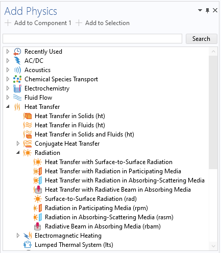
The available interfaces for modeling heating due to radiation.
Under the Heat Transfer > Radiation branch shown above, we find predefined couplings between the Heat Transfer in Solids interface and an interface for modeling radiation transport, as well as interfaces for modeling radiation transport only, without taking temperature changes into account. In this case, the temperature is not computed but prescribed in the user interface.
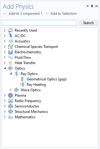
Under the Optics > Ray Optics branch, we find the Ray Heating interface, which couples the Heat Transfer in Solids interface with the Geometrical Optics interface, which uses a ray tracing technique to model the beam paths. Note that for modeling the temperature distribution, the interface is always the same — only the method and thus the interface for the calculation of the radiation transport differs.
How we consider the transport of radiation strongly depends on the material properties, as well as the size of the system, its temperature, and the nature of the radiation source. There are a few criteria that can help you choose the right interface. Nevertheless, each system has its own peculiarities and should be carefully examined.
Use Cases of the Different Interfaces
We want to take a look at common applications and discuss the applicability of the interfaces. One criteria to decide which interface is suitable is the characteristics of the radiation itself — Where does the radiative intensity have its maximum? This is related to the temperature of the radiation source. For a blackbody, the wavelength at which the radiative intensity has its maximum \lambda_\textrm{peak} (m) can be calculated by Wien’s displacement law:
with b\approx 2898\ \mu m\cdot K being Wien’s displacement constant.
For example, the Sun has its maximum in the visible range, whereas the peak for objects at room temperature is in the infrared range. The second aspect is the material properties that interact with the radiation, and the third aspect is the size of the system or the optical thickness, respectively.
Thermal Management of Electronics Components
Many electronics cooling applications follow the same principles. An electronic component heats up while operating. Heat sinks, which are often used for cooling, absorb the heat and release it to a surrounding fluid. The fluid then transports the heat away by forced and/or free convection and the interaction with radiation in the fluid is negligible.
The solid objects usually are opaque for radiation, and they emit radiation from their surfaces to the surrounding. To improve their performance to release heat by radiation, these surfaces are often coated to maximize the emissivity.
For most applications in this area, the Surface-to-Surface Radiation interface is the best choice to account for radiative heat transfer when the components are placed in an enclosure where all solid walls exchange heat by radiation. If the components are exposed to an open environment and their surfaces don’t exchange radiation between each other (convex shape), the radiative cooling can be modeled using the boundary condition Surface-to-Ambient Radiation within one of the Heat Transfer interfaces, and no additional equation for radiation needs to be solved.
The question of whether radiative heat flux is significant for a particular application at all or if it can be neglected depends on the:
- Temperature
- Material properties
- Convective and conductive cooling heat fluxes
It is always recommended to test whether radiation plays a role or not. This also always depends on the desired accuracy. The figure below shows the difference in the results with and without radiation taken into account, which leads to a temperature difference of 30K in this particular example.
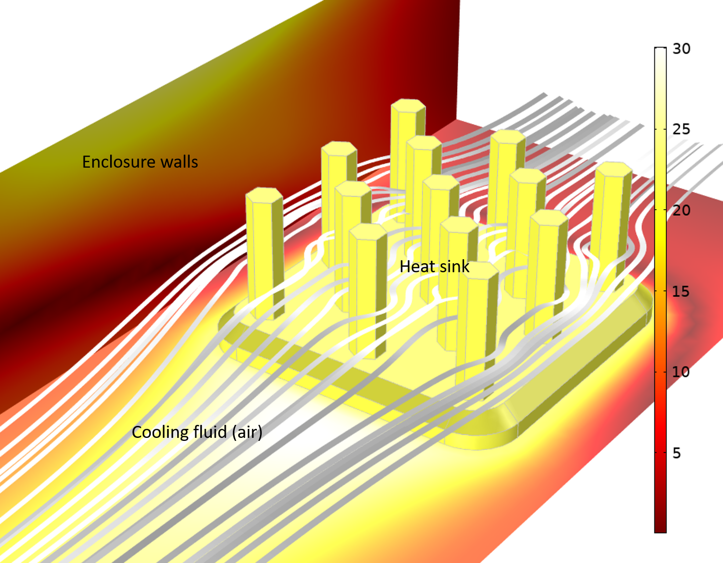
The tutorial model Heat Sink with Surface-to-Surface Radiation showing the temperature difference when radiation is considered vs. when it is neglected. The heat sink has a high emissivity, which causes a significant amount of radiation exchange to the channel walls. The air as a cooling fluid is transparent due to the small optical thickness.
Solar Irradiation
Solar irradiation has its maximum in the visible range and the interaction of solar radiation with the ambient air can be neglected. When sun rays hit an opaque surface, the radiation is absorbed and causes it to heat up. We know this phenomenon from our own experience: The side facing the Sun feels warmer than the side in the shade.
The Surface-to-Surface Radiation interface is therefore suitable for most applications with the Sun as radiation source. An illustrative tutorial model is the Sun’s Radiation Effect on Two Coolers Placed Under a Parasol model from the Application Library.
In some applications, the focus is on optimizing a system with respect to the beam path, as in the Solar Dish Receiver Designer app, where the local heat flux is to be maximized in order to heat steam for power generation, for example. In this case — when the optical path is critical — the Ray Optics interface is the right choice.
Collimated Beams
If the incident radiation that penetrates a homogeneous medium can be described as a collimated beam, and if scattering and (thermal) emission of the medium are negligible, the Radiative Beam in Absorbing Media interface is an accurate and very efficient way to solve this kind of radiation problem. It solves the Beer–Lambert law, which is commonly used in spectroscopy.
Other application areas include the attenuation of solar radiation by the atmosphere and the characterization of the attenuation of X-rays in CT scans.
A nice discussion of the different approaches for modeling laser material interactions is done in a previous blog post.
Combustion Process
Radiation from gases strongly depends on the composition of the gas. Depending on the components, the gas mixture absorbs only in certain wavelength ranges and is transparent to other wavelengths.
In industrial furnaces and combustion processes, gas radiation, along with convection, is the main heat transport mechanism. The reason for this is that the gases (or vapors) contain molecules that interact with radiation (e.g. CO2 or H2O). In many cases, the media also contain particles, which are the main source for scattering. In these cases, where absorption, emission, and scattering must be considered, the Radiation in Participating Media interface is the right choice.
Incident radiation for a prescribed temperature distribution in an industrial utility boiler. Left: no scattering, right: scattering with \sigma_\textrm{s}=0.9\ 1/m.
Glass
Glass as a material should meet various requirements when it comes to interaction with radiation. Window glass, for example, should allow light in the visible range to pass through but insulate against thermal radiation. There are various coatings for different purposes.
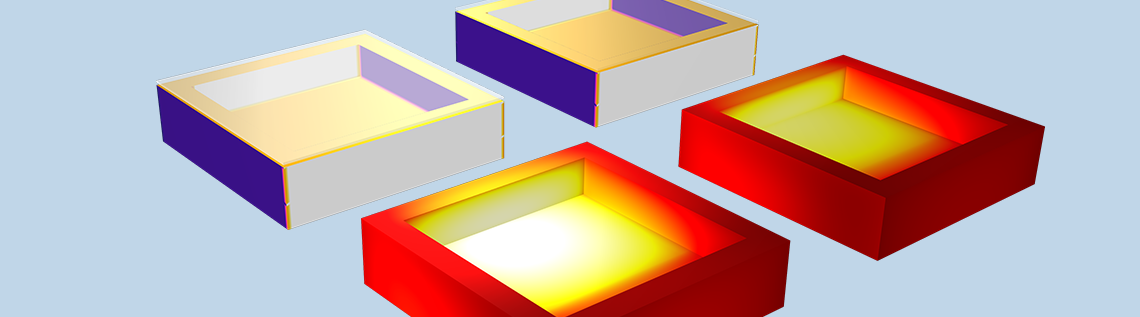
If you look at the area of application for glass, you will often be able to describe the glass as a semitransparent surface and thus the Surface-to-Surface Radiation interface is used. For example, the greenhouse effect can be modeled as shown in the box configuration below.
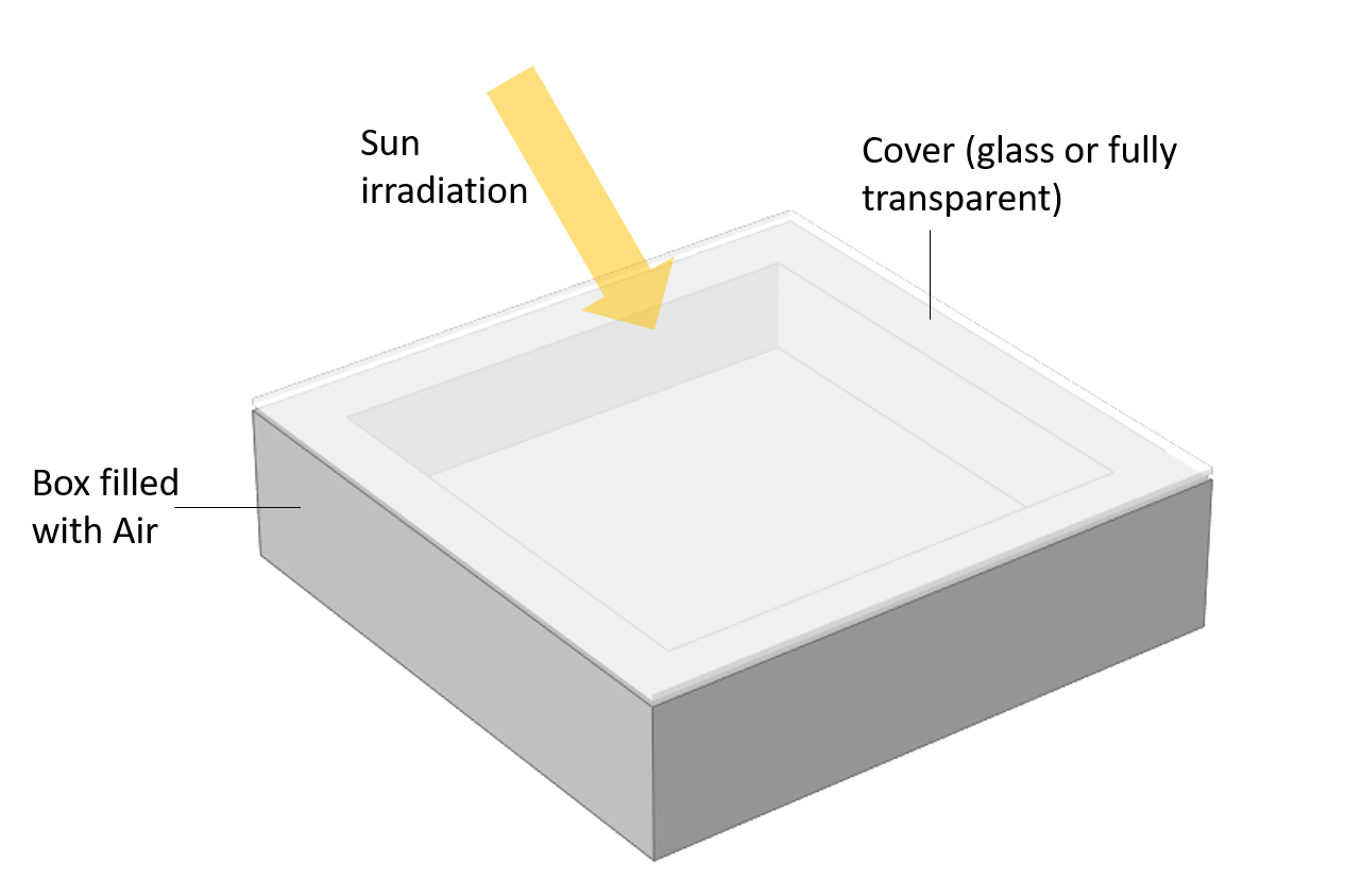
Setup for modeling the greenhouse effect. A box filled with air and covered with either a glass plate or a fully transparent plate. The inner walls are black (\varepsilon=1) and the outer walls are reflecting (\varepsilon=0.1).
For the box covered with the glass plate, which is transparent for shorter wavelengths (\lambda<2.5 \mu m, visible light) and opaque for larger wavelengths (\lambda>2.5 \mu m, infrared), the greenhouse effect can be observed. The black walls absorb all incident radiation, heat up, emit radiation according to their temperature at larger wavelengths for which the glass cover is opaque, and reflect this radiation back to the absorbing walls. This increases further the rise in the temperature of the absorbing walls.
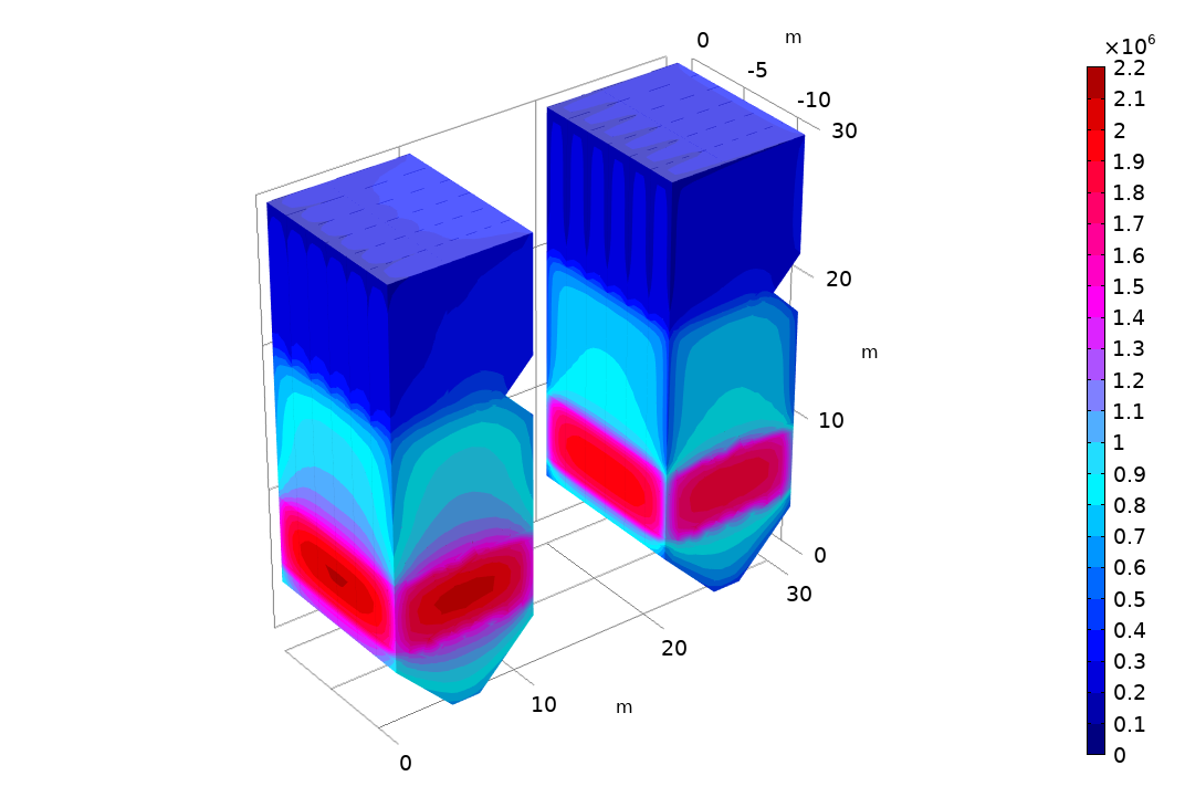
Temperature evolution in a box over one day illustrating the greenhouse effect. The 3D plot shows the incident radiation (top row) and temperature (bottom row) for a box with a glass plate (left column) and a fully transparent plate (right column). The temperature in the box with the glass plate increases significantly more, showing the greenhouse effect.
In contrast, the radiation transport inside glass plays an important role for its production, especially during cooling, because it is important that cooling takes place uniformly during the phase transition from the molten glass to the solid glass, so that no mechanical stresses occur. In this case, therefore, absorption and emission are important and the Radiation in Participating Media interface is the right choice.
Lenses
In the special case of lenses, as they are used in optical systems and often penetrated by high-power laser beams, the refractive index can change significantly due to temperature changes. In addition, temperature changes lead to structural deformation, which again leads to a shift of the beam direction.
For these cases, the Radiation in Participating Media interface is not suitable and the Ray Heating interface must be used. This interface can address in particular the phenomena in optical systems, such as diffraction, refraction, as well as the progression through coated objects. However, it is a requirement that the radiation source is defined with its power, and radiation does not occur solely on the basis of its temperature.
Compounds of Different Materials
How do we handle compounds of different materials, such as double-glazed windows, where different semitransparent media with wavelength-dependent properties and coatings are interacting? In this case, we could use the Ray Heating interface to calculate the mean values for the structure and use them within the interfaces under the Heat Transfer > Radiation branch.
Conclusion
We have discussed all aspects that need to be considered when modeling heat transfer by radiation. I hope this blog post helps you find the appropriate interface for your application. If you are further interested in the underlying theory, check out the following blog posts:
- 4 Methods to Account for Radiation in Participating Media
- Understanding Classical Gray Body Radiation Theory
- Modeling Thermally Induced Focal Shift in High-Powered Laser Systems
Reference
- M.F. Modest, Radiative Heat Transfer, Academic Press, 2003.

Comments (4)
Ivar KJELBERG
March 24, 2021Hi,
Nice Blog, good examples showing the advantages of using COMSOL for HT and S2S “physics”.
A simple reminder, for us users, we are perhaps not all aware that the Wiens displacement law parameter “b” is part of COMSOL’s internal prefixed physics variables, and may be used directly as “b_const” in our equations.
We may also calculate it from scratch, but the integration required to get to that value takes some time. So using COMSOL’s internal physics constants if far more efficient 🙂
Sincerely,
Ivar
Steven Delrue
August 6, 2021Dear Nancy,
Thank you for this interesting blog. Can the example for the air-filled box be downloaded somewhere?
Kind regards,
Steven
Nancy Bannach
August 6, 2021 COMSOL EmployeeDear Steven,
good point. Yes, the model is now available here:
https://www.comsol.com/model/greenhouse-effect-98061
Best regards,
Nancy
Tae Lim
August 8, 2021Dear Nancy,
Thank you for the interesting blog and sharing the example file. Could you also make it available to previous COMSOL versions? I am using 5.5 and cannot view the example model. Thank you
Regards,
Tae